Integrating Fault Tree Analysis (FTA) into Model-Based Systems Engineering (MBSE) brings safety assessment into the same modelling workflow as system definition. Safety engineers can evaluate failure paths, revise analysis inputs and investigate design decisions while keeping their work connected to the system model. This connection matters when a design evolves: the failure logic and its assumptions need to remain aligned with the engineering information they describe.
The SysML v2 FTA project described here implements that connection through a dedicated safety metamodel and a web application linked to a Systems Modeling Language version 2 (SysML v2) model. Engineers work in the application to inspect the tree, calculate probabilities, explore minimal cut sets and edit supported safety parameters. Those parameter changes are reflected in the model, enabling an analysis workflow that combines a dedicated safety interface with model-owned engineering data.
What integrating FTA with MBSE enables
Maintaining a fault tree separately from the system model creates coordination work. Engineers must transfer relevant information, track changes in both environments and check which assumptions a result represents. Connecting the analysis to model elements reduces the need to recreate those inputs and gives safety and systems engineers a shared basis for reviewing them.
The integration supports three practical activities. During analysis preparation, engineers reuse explicitly modelled events, gates and parameters. During evaluation, they inspect the failure paths and results through the application. During iteration, they revise supported inputs through that same interface and reflect the changes in the model. This makes safety analysis usable throughout design development, with a shorter path from an engineering question to a revised assessment.
For example, a change in mission duration raises a specific safety question: how does the revised exposure affect the defined top event? The engineer can update the supported mission-time parameter, evaluate the tree again and compare configurations with their assumptions visible. Keeping the revised input connected to the model reduces the manual reconciliation needed before the next analysis.
These benefits depend on explicit safety modelling. A system architecture alone does not specify every failure condition, dependency or assumption. Engineers still define the top event and failure logic, and review their relevance when the design changes.
How the SysML v2 FTA workflow connects model and analysis
A reusable safety metamodel defines the events, gates and inputs that the application recognises in the system model. The application retrieves those elements, reconstructs their fault-tree relationships and passes the supported analysis inputs to a calculation service. The solver returns the top-event probability and minimal cut sets for inspection in the application.
The connection also supports updates in the other direction: supported parameter edits made in the application are reflected in the system model. Engineers can therefore use an interface designed for safety analysis while maintaining those inputs in the MBSE environment. The scope of this editing capability is the supported safety parameters; changes to architecture and failure logic still require the corresponding modelling work.
Each layer has a distinct responsibility. The model holds the engineering definitions and inputs, the metamodel gives them safety-related meaning, the application provides the working interface, and the solver performs the calculations. Preserving the meaning of the data across these layers is essential to keeping analysis and model aligned.
Anzen’s earlier work on model-based fault trees in Capella addresses a related engineering need. This project develops that connection through SysML v2 and a web-based analysis interface.
Defining safety information in the model
SysML v2 provides the modelling language; the project supplies the fault-tree vocabulary. The safety metamodel introduces a common Element definition and three specialisations: Event, Gate and Transfer. Reusing these definitions across system models gives the integration layer a consistent way to recognise analysis objects.
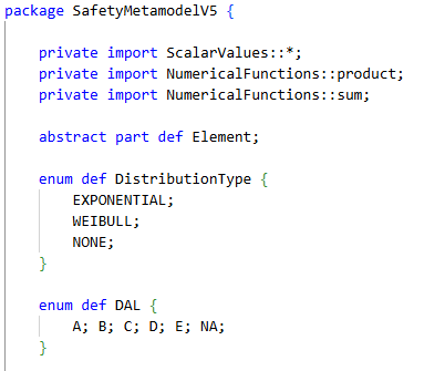
An Event represents a failure or undesired condition. Its attributes include failure rate, mission time, a distribution selection and information about latent failures. Keeping these inputs in the model exposes the assumptions behind a probability and gives engineers a place to revise them when operating conditions change.
The current analytical workflow concentrates on exponential failure models. Although the distribution enumeration also includes Weibull, representing that option in the metamodel does not establish support throughout the calculation chain. Extending the analysis requires compatible parameters and solver behaviour as well as a model definition.
Design Assurance Level (DAL) is also represented as an attribute. It records an engineering assignment associated with the model element; calculating a failure probability does not automatically determine that assignment.
Keeping exposure and latent-failure assumptions explicit
Mission time and failure rate need a consistent unit convention. If exposure is expressed in hours, the corresponding rate must use compatible units. The event definition makes mission time explicit through the missionTimeHours attribute.
Latent failures need additional context because they can remain undetected until an inspection or test. The metamodel therefore includes an isLatent flag and testIntervalHours. These fields allow the analysis to distinguish inspection-related exposure from ordinary mission exposure.
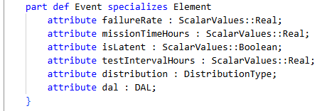
A test interval alone does not fully define a latent-failure calculation. Engineers must also establish the detection and restoration assumptions and the probability measure required by the assessment. For example, average unavailability over a test interval and the probability of failure by its end answer different questions. The selected calculation convention must remain consistent with the assessment objective.
Building gates and reusable tree structures
Gates combine events through Boolean logic. In this implementation, an AND gate requires all its inputs to occur, while an OR gate requires at least one. Inputs can be events or other gates, allowing several levels of failure logic.
Consider two redundant paths that provide the same function. If both must fail for that function to be lost, an AND gate can represent that relationship. A separate failure capable of disabling the function on its own would form another path to the top event. The engineer must still account for shared resources and common causes when defining the tree.
The Transfer definition references an element in another subtree. This supports reuse without requiring every visible occurrence to represent a distinct failure.
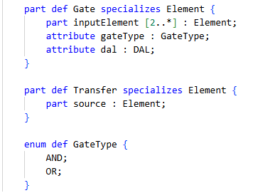
Reused structures also create an analytical requirement: the calculation must preserve event identity. Two references to the same basic event are not two independent failures. Likewise, Boolean gate definitions alone do not establish statistical independence. These distinctions matter when translating the model into solver inputs.
Working with the connected fault tree in the application
When an engineer selects a project, the application retrieves the relevant model elements and interprets their types and relationships using the safety metamodel. It also reads the parameters required for supported calculations. A transformation layer converts this information into the structure used by the diagram and analysis service.
The graphical view is the entry point to an analysis workspace. Engineers can inspect the failure logic, use textual and tabular views to examine event parameters, run supported calculations and investigate the resulting cut sets. They can also edit supported inputs from the application and reflect those changes in the system model. The diagram gives these actions context by showing where an event sits in the failure logic.
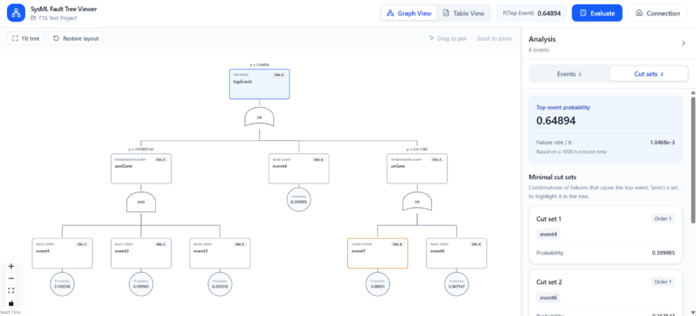
The value of this workspace comes from the connection between those actions and the underlying model elements. An event inspected in the tree has modelling parameters that feed the calculation; revising a supported parameter provides an input for the next evaluation. The transformation must preserve the selected top event, gate connections, event references and applicable inputs so that engineers work with the intended analysis throughout this cycle.
Evaluating probabilities and minimal cut sets
The application calculates supported basic-event probabilities from their modelling parameters, then sends those values and the tree structure to a separate calculation service. The solver returns the top-event probability and minimal cut sets.
The top-event probability expresses the likelihood of the defined undesired event under the analysis assumptions. Its interpretation depends on exposure, failure models and dependencies. A result should therefore be reviewed with those inputs, rather than treated as an intrinsic property of the architecture.
Minimal cut sets explain which combinations of basic events are sufficient to produce the top event. A set is minimal when removing any member makes it insufficient. Minimal sets can have different numbers of members; the term does not mean that only the combinations with the fewest events are retained.
Selecting a cut set highlights its events in the diagram. This connects a calculated result to the failure logic and helps the engineer investigate individual failure paths. A single-event cut set, for example, identifies an event that is sufficient by itself within the modelled logic.
The NRC’s SAPHIRE technical reference describes fault-tree algorithms, minimal cut sets and probability calculations under different repair and mission-time assumptions. These analytical distinctions remain relevant when the inputs originate in a system model.
Editing analysis inputs and reflecting changes in the model
An engineer investigating a failure path can revise a supported event parameter directly in the application. The change is reflected in the system model, and a subsequent evaluation uses the revised input. This closes the working loop between model data, safety analysis and parameter refinement: the application serves as a practical interface for working with the connected engineering information.
Shared defaults and event-specific overrides need different treatment. A project may define a common mission time, while one event requires a different exposure duration. An override lets that event use its own value without changing the assumption for every other event.
For review, the effective value matters as much as the stored default. Engineers need to understand whether an event inherits the project assumption or uses an override when interpreting a result. Making that distinction explicit helps explain why a change affects some branches of a tree and leaves others unchanged.
This emphasis on connected inputs also appears in Anzen’s work on model-based reliability analysis, where architecture and implementation information provide context for analysis.
Comparing configurations with their assumptions
The application can save evaluated configurations and compare them side by side. A saved configuration captures the tree structure, relevant inputs and calculated results at a particular point in the engineering process.
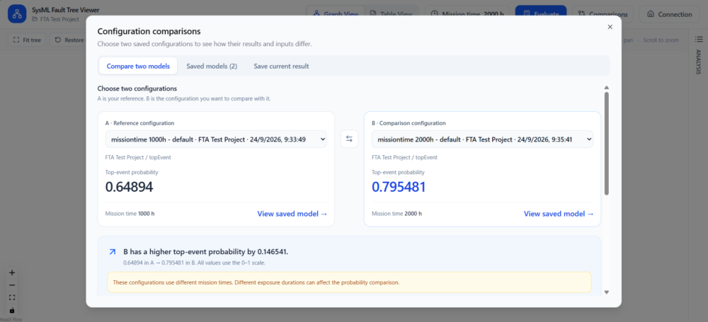
In the illustrated example, the displayed top-event probability changes from 0.64894 to 0.795481. The comparison also exposes the different mission times. These are demonstration results, not evidence of a real system’s safety performance.
The exposure difference changes how the comparison should be read. A higher probability over a longer mission does not, by itself, establish that an architecture has become less reliable. To investigate an architectural change, engineers should compare equivalent operating assumptions or identify the effect of each changed input.
Saved configurations therefore provide more than a history of numerical outputs. They preserve context for investigating why results differ, whether the cause is a revised design, a changed failure-rate input or a different exposure assumption.
Connecting safety assessment to design iteration
Integrating FTA with MBSE lets engineers use safety analysis as part of design iteration. The model supplies the failure logic and its inputs; the application lets engineers evaluate that logic, investigate results and revise supported parameters while keeping them connected to the model. Saved configurations provide a basis for reviewing how changed assumptions affect the assessment.
The practical advantages are reduced re-entry of modelled inputs, clearer access to analysis assumptions and a connected workflow for investigating changes. Systems and safety engineers can discuss the modelled failure paths and the parameters behind a result together. Engineering review remains essential as architecture and operating conditions evolve, and the integration gives that review a consistent information base.
To explore this workflow for your programme, contact Anzen with a representative system model and a safety-analysis use case. A useful starting point is one defined top event, its supporting failure logic and the parameter changes your team needs to evaluate.
About the authors
Javier Amigo is an Aerospace Engineer specializing in systems engineering, with a growing focus on Model-Based Systems Engineering (MBSE), simulation, and safety.
At Anzen, he contributes to the analysis and development of complex aerospace systems across projects in the United Kingdom and North America, alongside his work on ASCEND and VARIANT.


